This article is my K8S deep dive article, What is under the hood of Kubernetes? We will talk about the Definition and Components.
Without a doubt, you heard a lot about Kubernetes, such as "Kubernetes is the operating system of distributed applications," "Kubernetes is the best container orchestration tool," "Kubernetes is the best platform for running Cloud Native applications," etc. Are you curious about what it is precisely and how it can be both fundamental and versatile? Buckle up. Let's see what is under the hood of Kubernetes?
Definition Deep Dive
Firstly, by officially defined,
Kubernetes/K8S, is an open-source system for automating deployment, scaling, and management of containerized applications.
As the definition suggested, K8S can run and manage your containerized applications. To approach that, K8S employs the following four pillars:
- Resource Definition: K8S defines the application runtime lifecycle as a couple of resource types, such as Deployment for molding a release of a stateless application, StatefulSet for scheming a release of a stateful application, ReplicaSet for outlining the replications of an application, Pod for describing the specification of a running copy, etc. The properties of each resource identify the resource states.
- Declarative API: Kubernetes API-Server exposes a suite of Declarative APIs for Resources as a centric entry point for submitting and modifying the desired status of specific resources.
- Event Queues: Each Resource has a corresponding Event Queue to stream the state changes event, such as autoscaling event
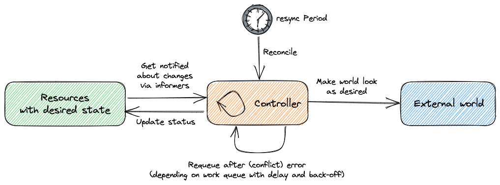
CPU Usage is 80%, replication set eventScaled to 8, Pod scheduling eventAdded 2 Podsor Kubelet Pod binding eventBound Pod to Kubelet "X". - Resource Controller: For each particular resource type, Kubernetes introduces a Controller for constantly reconciling between the current resource status and the desired status by spinning in a loop, the well-known Kubernetes Control-Loop. In robotics and automation applications, a control loop is a non-terminating loop that regulates the system's state. In Kubernetes, a control loop watches the shared state of a specific resource through the Event Queue of kube-apiserver and makes changes attempting to move the current state towards desired.

These four pillars constitute a reconciliation mechanism over time, which makes the application auto-healing possible. For instance, our Service-A has three replications after being released successfully, which are all running well. At one point, AWS needs to retire the worker node that one replica of Service-A is running on. Based on the reconciliation, we are very safe and confident to do the retirement. After we terminate that worker node, the replication run on it would be deleted. Then the replication state of the Service-A Deployment turns to 2, which is not the desired state, 3. And this is an event that triggers the ReplicaSet controller to create a new replication to approach the desired state of replication number, 3.
To conclude, Kubernetes is absolutely a Control Theory based automatic engine for managing the application through state transitions in the lifetime of that application. Event Queues are the pipes, and Events are the oil, Resource Definitions are the states on the dashboard, API-Server provided APIs are the knobs on the dashboard that you can set and update the metric values.

Components Deep Dive
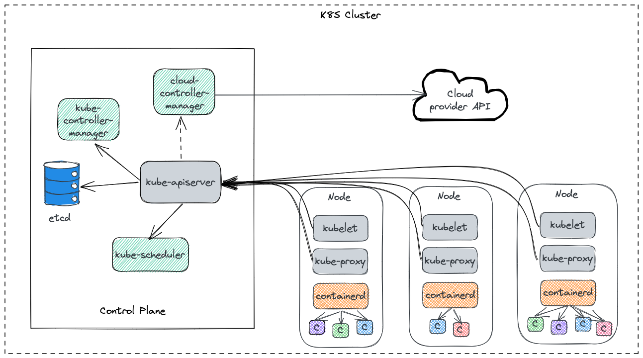
We can take this process one step further. Let's dive into the details of Kubernetes to see how it implement those above pillars. The following figure demonstrates the components of Kubernetes, including
Control Plane
- A central server of APIs –> kube-apiserver
- A manager of K8S resource controllers –> kube-controller-manager
- A manager of Cloud resource controllers –> cloud-controller-manager
- A scheduler of Pod –> kube-scheduler
- A data storage –> etcd
Data Plane (For each node)
- One data agent as a daemon –> kubelet
- One network proxy as a daemon –> kube-proxy
- One container runtime engine as a daemon –> contianerd/docker

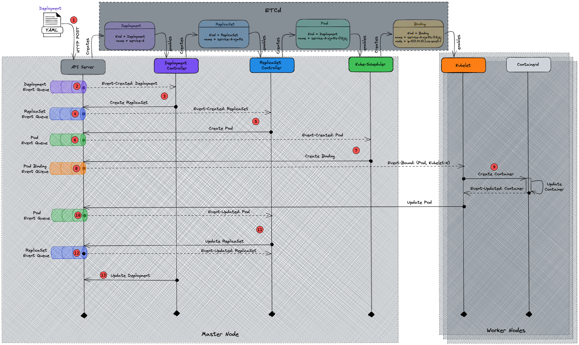
They work together to run and manage the application containers dynamically and effectively. But how does Kubernetes chain them together, and what is the glue between any two components? Let's use a stateless microservice, service-A, as an example to demonstrate the whole process of releasing an application on Kubernetes. Below is a UML sequence diagram, which shows the cascading effects between different components, followed by an explanation of each step.

apiVersion: apps/v1
kind: Deployment
metadata:
  labels:
    app: service-A
  annotations: {}
  name: service-A
  namespace: service-A
spec:
  replicas: 3
  selector:
    matchLabels:
      app: service-A
  strategy:
    rollingUpdate:
      maxSurge: 1
      maxUnavailable: 1
    type: RollingUpdate
  template:
    metadata:
      labels:
        app: service-A
      annotations: {}
    spec:
      containers:
      - env:
        - name: BUILD_NO
          valueFrom:
            configMapKeyRef:
              key: BUILD_NO
              name: service-A
        image: "dockerhub.io/service-a:build-293"
        imagePullPolicy: Always
        name: service-A
        securityContext: {}
        ports:
          - name: http
            containerPort: 8199
            protocol: TCP
        resources:
          limits:
            memory: 500Mi
          requests:
            memory: 128Mi
        terminationMessagePath: /dev/termination-log
        terminationMessagePolicy: File
      dnsPolicy: ClusterFirst
      securityContext:
        fsGroup: 1000
        runAsUser: 1000
      nodeSelector:
        pool-type: large
      restartPolicy: Always
      schedulerName: default-scheduler
      terminationGracePeriodSeconds: 15
      serviceAccountName: service-A
      volumes:
      - name: service-A
        secret:
          defaultMode: 420
          secretName: service-A
- As a trigger of this release, users apply a Deployment manifest as above, a typical K8s Deployment, to API-Server (HTTP POST)
- Kube-apiserver creates a Deployment resource based on the manifest declared, then produce an event
Created: Deployment(service-A)to the Deployment Event Queue, - Deployment Controller, which is watching Deployment Event Queue, consumes the event
Created: Deployment(service-A)from the queue. As a follow-up action, it applies a ReplicaSet manifest as theDeployment(service-A).specdeclared to kube-apiserver. Then Deployment Controller keeps running in its Control Loop to reconcileDeployment(service-A).statusbetween Ready or not. The status of ReplicaSet this Deployment creates would be a criterion of the reconciliation, - Kube-apiserver creates a ReplicaSet resource, and after which Deployment Controller produces an event
Created: ReplicaSet(service-A-xjm8s)to the ReplicaSet Event Queue, - ReplicaSet Controller, which is watching ReplicaSet Event Queue, consumes the event
Created: ReplicaSet(service-A-xjm8s)from the queue. And then appliesDeployment(service-A).spec.replicasPod manifests, based on theDeployment(service-A).spec.templatedeclared, to kube-apiserver. Also, same behavior as Deployment Controller, ReplicaSet Controller runs in its Control Loop to reconcileReplicaSet(service-A-xjm8s).statusbetween Ready or not, which replies on the status of each Pod it creates, - For each Pod manifest, kube-apiserver creates a Pod resource, after which ReplicaSet Controller produces an event
Created: Pod(service-A-xjm8s-xxxxx)to the Pod Event Queue, - Kube-scheduler, which is watching Pod Event Queue, consumes the event
Created: Pod(service-A-xjm8s-xxxxx)from the queue. And then applies aBound(name=service-A-xjm8s-xxxxx, node=ip-100.14.10.1.us-east-1)manifest, based onDeployment(service-A).spec.template.containers.resourceandDeployment(service-A).spec.template.nodeSelectordeclared, to kube-apiserver. - For each Binding manifest, kube-apiserver creates a Binding resource, after which Kube-Scheduler produces an event
Bound(name=service-A-xjm8s-xxxxx, node=ip-100.14.10.1.us-east-1)to Pod Binding Event Queue, - Kubelet, which is watching Pod Binding Event Queue, consumes the event
Bound(name=service-A-xjm8s-xxxxx, node=ip-100.14.10.1.us-east-1)from the queue. And then instructs the container runtime on the worker node, ContainerD or DockerD, to create containers asDeployment(service-A).spec.template.spec.containersspecified. Once that completes, Kubelet sends an HTTP Post request to kube-apiserver to updatePod(service-A-xjm8s-xxxxx).statusas Ready, - Kubelet produces an event
Updated: Pod(service-A-xjm8s-xxxxx, status=ready)to Pod Event Queue, - ReplicaSet Controller, which is running in its Control Loop and watching Pod Event Queue, consumes the event
Updated: Pod(service-A-xjm8s-xxxxx, status=ready)from the queue for each Pod resource. After it gets allUpdatedEvents of all the pods it created, which is reconciling in the Control Loop, ReplicaSet Controller sends to kube-apiserver an HTTP Post request to update theReplicaSet(service-A-xjm8s).statusas Ready, - ReplicaSet Controller produces an Event
Updated: ReplicaSet(service-A-xjm8s, status=ready)to Pod Event Queue, - Deployment Controller, which is running in its Control Loop and watching ReplicaSet Event Queue, consumes the event
Updated: ReplicaSet(service-A-xjm8s, status=ready)from the queue. And then Deployment Controller sends to kube-apiserver an HTTP Post request to updateDeployment(service-A).statusas Ready.
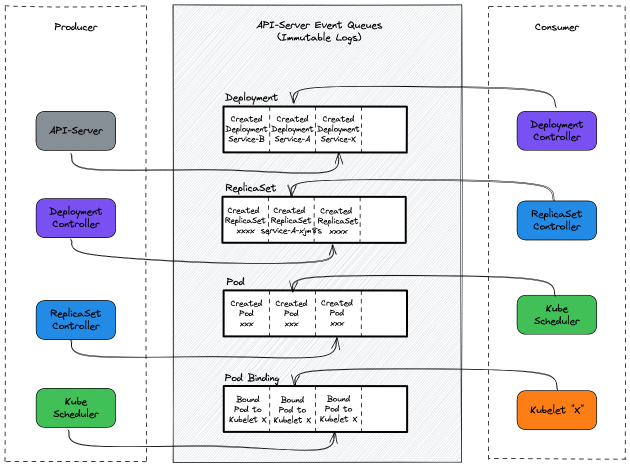
To make it more straightforward, we could understand this whole process from the Event Queues perspective. The following is a diagram including the Event Queues introduced above, which cooperated to achieve Deployment as ready and manage the status of that Deployment over time.

Summary
In summary, we talked about what Kubernetes is and how it works based on the definition and components deep dive. In the following article, we will touch on the implementations of some critical components and how they are chained together at the code level.

